Solution Architecture View (Archimate/TOGAF) with an LLM Assistant
This playbook guides you through using a Large Language Model (LLM) assistant to generate a solution architecture diagram following the Archimate specification. It covers framing your prompt, getting the output in PlantUML language, and rendering it with a PlantUML editor.

Technologies Used
🎯 Objective
Generate a solution architecture diagram (in Archimate specification) using PlantUML language, with the help of an LLM-based assistant (like ChatGPT, Claude, Gemini, etc.), and render it visually using a PlantUML editor.
My recommendation: AI Studio (Google)
🛠️ 1️⃣ Preparation
✅ Know your architectural scope and context
Define what the architecture diagram should represent (e.g. high-level business services, application layers, technology components).
Examples:
- A new microservices deployment
- A data pipeline
- Integration with external systems
✅ Identify the key elements you want in the diagram:
- Business Actors, Roles, Processes, Services
- Application Components, Services, Interfaces
- Technology Nodes, Devices, System Software
- Flows, relationships, dependencies
✅ Choose a diagram view:
- Business view
- Application view
- Technology view
- Or a combined layered view
📝 2️⃣ Frame Your Prompt to the LLM Assistant
💡 Example prompt template:
Prompt:
“I want to generate a solution architecture diagram following the Archimate specification.
Here’s the scope: [brief description of what it represents].
Elements to include: [list key components, roles, relationships].
Output it in PlantUML language, using Archimate notations.
Ensure the PlantUML diagram is complete and ready to be visualized in a PlantUML editor.”
You can also ask for help to get started by sharing the overall context of the solution. Any baseline suggestions would be a great starting point.
📥 3️⃣ Get the PlantUML Code
🟩 The LLM will typically generate a code block containing the PlantUML script.
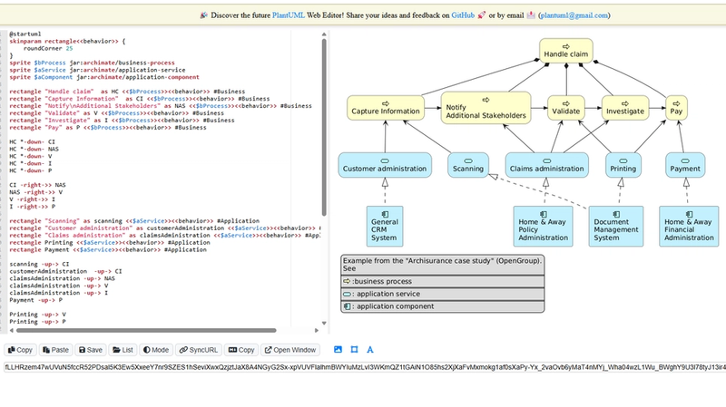
Example snippet it might provide:
@startuml
skinparam rectangle<<behavior>> {
	roundCorner 25
}
sprite $bProcess jar:archimate/business-process
sprite $aService jar:archimate/application-service
sprite $aComponent jar:archimate/application-component

rectangle "Handle claim"  as HC <<$bProcess>><<behavior>> #Business
rectangle "Capture Information"  as CI <<$bProcess>><<behavior>> #Business
rectangle "Notify\nAdditional Stakeholders" as NAS <<$bProcess>><<behavior>> #Business
rectangle "Validate" as V <<$bProcess>><<behavior>> #Business
rectangle "Investigate" as I <<$bProcess>><<behavior>> #Business
rectangle "Pay" as P <<$bProcess>><<behavior>> #Business

HC *-down- CI
HC *-down- NAS
HC *-down- V
HC *-down- I
HC *-down- P

CI -right->> NAS
NAS -right->> V
V -right->> I
I -right->> P

rectangle "Scanning" as scanning <<$aService>><<behavior>> #Application
rectangle "Customer administration" as customerAdministration <<$aService>><<behavior>> #Application
rectangle "Claims administration" as claimsAdministration <<$aService>><<behavior>> #Application
rectangle Printing <<$aService>><<behavior>> #Application
rectangle Payment <<$aService>><<behavior>> #Application

scanning -up-> CI
customerAdministration  -up-> CI
claimsAdministration -up-> NAS
claimsAdministration -up-> V
claimsAdministration -up-> I
Payment -up-> P

Printing -up-> V
Printing -up-> P

rectangle "Document\nManagement\nSystem" as DMS <<$aComponent>> #Application
rectangle "General\nCRM\nSystem" as CRM <<$aComponent>>  #Application
rectangle "Home & Away\nPolicy\nAdministration" as HAPA <<$aComponent>> #Application
rectangle "Home & Away\nFinancial\nAdministration" as HFPA <<$aComponent>>  #Application

DMS .up.|> scanning
DMS .up.|> Printing
CRM .up.|> customerAdministration
HAPA .up.|> claimsAdministration
HFPA .up.|> Payment

legend left
Example from the "Archisurance case study" (OpenGroup).
See
====
<$bProcess> :business process
====
<$aService> : application service
====
<$aComponent> : application component
endlegend
@enduml
🎨 4️⃣ Visualize the Diagram
🔧 Choose a PlantUML Editor:
- PlantUML Live Editor
- PlantText
- Visual Studio Code extension (PlantUML plugin)
- IntelliJ IDEA PlantUML plugin
- Local setup with Java and Graphviz
🔗 Steps to Render:
- Copy the entire PlantUML code provided by the LLM.
- Paste it into the chosen editor.
- Hit “Refresh” / “Generate” / “Preview” to render the diagram.

🧰 5️⃣ Validate and Refine
✅ Check if the diagram accurately represents your intended architecture.
✅ If needed, refine the prompt:
- “Can you add relationships between component X and component Y?”
- “Please include more details about data flows or interfaces.”
- “Use proper Archimate viewpoints for better clarity.”
You can iterate with the LLM to enhance the diagram’s fidelity.
🪄 6️⃣ Tips for Better Results
🌟 Be explicit about relationships and viewpoints (e.g. “Show me a layered view separating business, application, and technology layers”).
🌟 Ask for documentation or labels if clarity is essential (e.g. “Add descriptions to components to explain their roles”).
🌟 Use bullet points or tables in the prompt to organize the details for better LLM understanding.
🌟 Save PlantUML scripts for version control and documentation purposes.
🎉 Outcome
By following this cookbook, you’ll get:
✅ A clear prompt for the LLM
✅ A PlantUML-ready Archimate diagram
✅ Visual renderings of your architecture
✅ A process you can repeat for other architecture needs